Introduction
Operational amplifiers is an essential component in electronic devices.

Operational amplifiers (op amps) are incredibly useful high-performance differential amplifiers that can be employed in a number of amazing ways. A typical op amp is an integrated device with a non-inverting input, an inverting input, two dc power supply leads (positive and negative), an output terminal, and a few other specialized leads used for fine-tuning. The positive and negative supply leads, as well as the fine-tuning leads, are often omitted from circuit schematics. If you do not see any supply leads, assume that a dual supply is being used. Note that we have labeled the supply voltages +\(V_{s}\) and −\(V_{s}\), as they are usually the same. However, they do not need to be.
Terminology
Loading Effect
When load affects the power source then it is called Loading effect. For example, let’s suppose there is a circuit with a voltage source and a series resistor. If the voltage source turns on, current will flow in the circuit. But if the voltage source + pole-to-ground short failure occurs in a circuit, circuit equivalent impedance will be 0 and the current diverges (voltage converges to 0).
BJT
A bipolar junction transistor is a three-terminal semiconductor device that consists of two p-n junctions which are able to amplify or magnify a signal. It is a current controlled device. The three terminals of the BJT are the base, the collector, and the emitter. A signal of a small amplitude applied to the base is available in the amplified form at the collector of the transistor. This is the amplification provided by the BJT. Note that it does require an external source of DC power supply to carry out the amplification process.
Structure
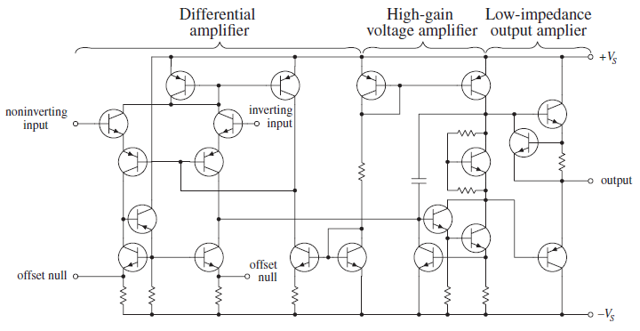
What is important here is not to focus on understanding the op amp’s internal circuitry but instead to focus on memorizing some rules that individuals came up with that require only working with the input and output leads. This approach seems like a “cop- out,” but it works.
Basics
- Op-Amp also have the loading effects problem.
- Most op amps are voltage amplifiers.
Ideal OPAMP
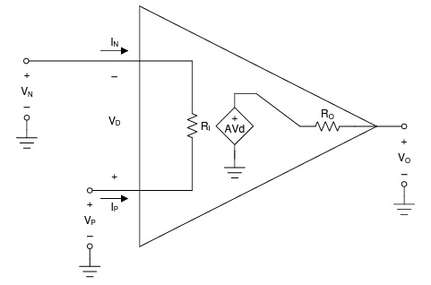
The ideal model makes three simplifying assumptions:
- Gain is infinite a = ∞
- Input resistance is infinite \(R_{i}\) = ∞
- Output resistance is zero \(R_{o}\) = 0
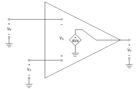
The ideal op amp model was derived to simplify circuit calculations. With simplifying assumptions, we can ignore loading effects.
Operation
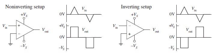
By itself, an op amp’s operation is simple. If the voltage applied to the inverting terminal V− is more positive than the voltage applied to the non-inverting terminal V+, the output saturates toward the negative supply voltage −\(V_{s}\). Conversely, if V+ > V−, the output saturates toward the positive supply voltage +\(V_{s}\).
Open-Loop
\(V_{out} = A_{o}(V_{+} - V_{-})\)
Rearranging the open loop gain equation, we get \(V_{out} \over A_{o} = (V_{+} - V_{-})\). Since \(A_{o}\) is infinite, \(V_{+}\) and \(V_{-}\) is almost same all the time. So, it can be regarded that non-inverting input and inverting input are short-circuited.
Closed-Loop
When voltage is “fed” back from the output terminal to the inverting terminal (this is referred to as negative feedback), the gain of an op amp can be controlled—the op amp’s output is prevented from saturating.
Applications
Buffer, Inverting Amplifier, Non-Inverting Amplifier, Integrator, Diferrentiator

References
1. Paul Scherz, Simon Monk - Practical Electronics for Inventors, 4th Edition
2. BYJU's - Bipolar Junction Transistor